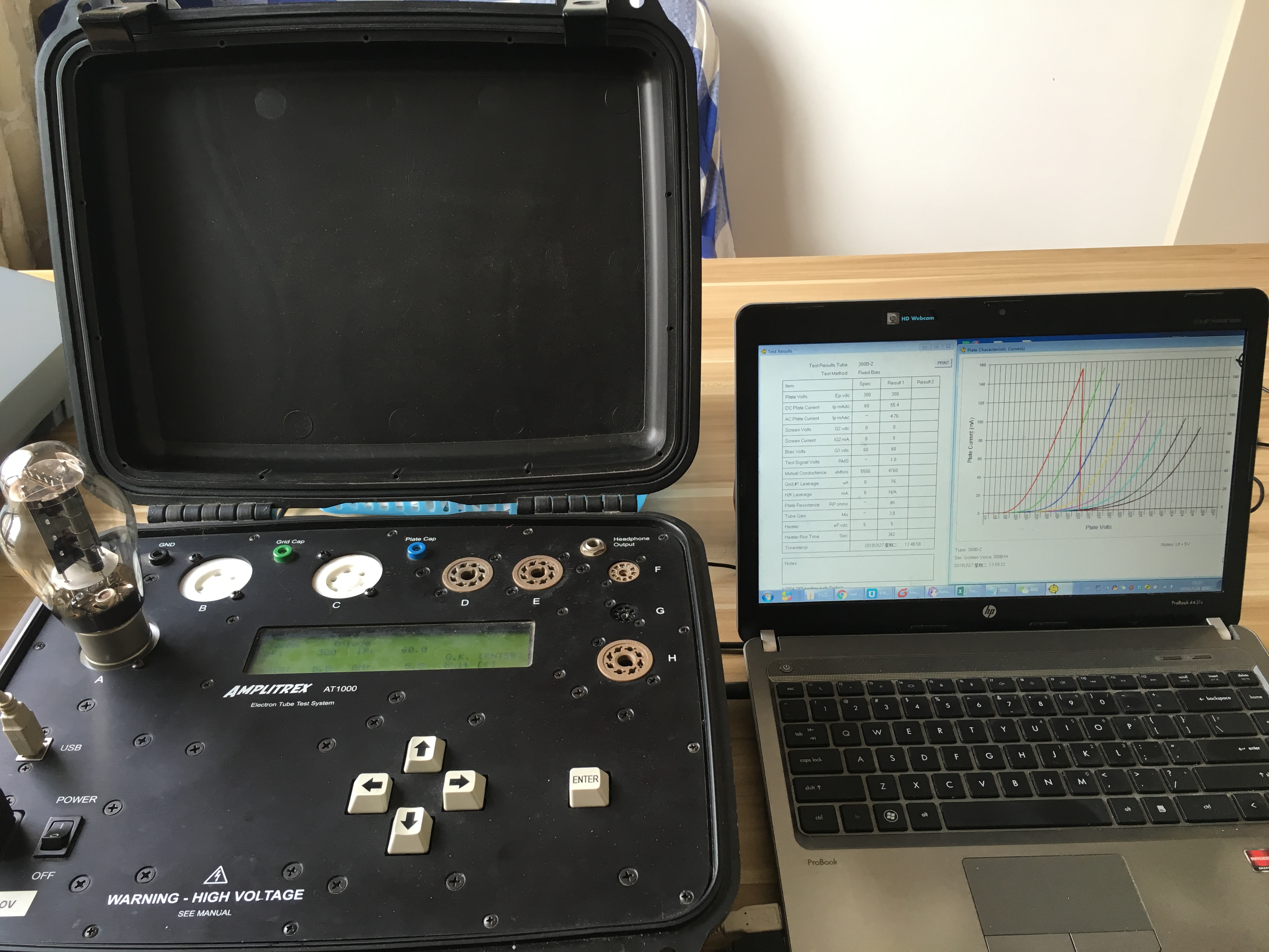
1. What are you are use the test system?
We use AT1000 tube test system, which the best equipment currently available.

2.What parameters can you provide for the tubes?
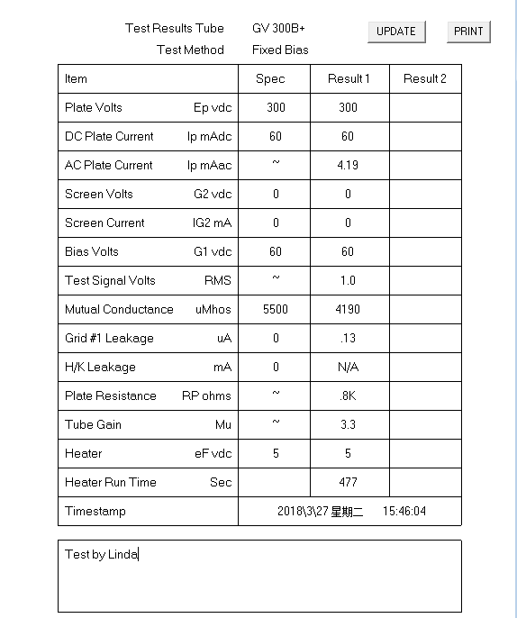
Normally, we provide plate current and transconductance.
If the customer has additional requirements, we can provide the test results of the following table(This part requires extra service charge):

3.What is a gas current? What is the harm of the gas current?
If there is residual gas inside the tube, the ion current flowing in the gas between the plate or screen and the grid causes the grid to become more positive (less negative).
In the case of a small preamp tube like a 12AX7 or EF86, anything infinitesimal of gas current will likely cause problems in the application circuit. Noise may be excessive, and/or the tube may not establish its correct operating point.
With a power tube like a 6L6, the interpretation must be different. Power tubes typically show a few milliamperes of gas-induced current increase, even if they are good. This is because in these tubes, plate temperatures are generally much higher and there is more surface area on the plate and other tube components which naturally outgass somewhat as it heats up. Also, because these tubes normally operate with several tens of milliamperes, or even over 100 milliamperes, a few mA of Gas current is OK. With power tubes, a gasinduced current increase of less than 10 percent of normal plate current is OK in most application circuits.
4.why do the tubes need match, and what are the matching criteria?
Vacuum tubes can be matched for use in balanced circuits, such as pushpull output or fully-differential preamplifier use. Single-section tubes can be matched to each other, and dual section tubes can have their sections matched as well as establishing a match between tubes
For power output tubes, some amplifiers have DC and AC balance controls. These controls can null out some of the variance in tube parameters. In parallel (SEP) and push-pull parallel power tube operation, close matching is essential for maximum performance. There are generally no separate bias and drive controls when tubes are run in parallel, and if the tubes don’t share the AC and DC loads symmetrically, power output and distortion will suffer greatly.
Differential audio and instrumentation amplifiers achieve best performance when matched tubes are used. Quite often, miniature dual triodes are employed. These can have their sections matched, or all the tubes in a signal chain can be matched. The circuit topology dictates which is more important, but full matching for this type of equipment guarantees best performance.
To match tubes by emission, use the Fixed Bias Mode, and compare the resulting plate currents measured during the test. The closer the values, the better the match. In push-pull power output stages, the emission match should be within 5% if there is no DC balance control or separate bias adjustment for each tube. Even with these adjustments, closely matching the emission of each tube greatly improves performance and long-term reliability.
To match tubes by transconductance, first make sure that the emission is within 10% for the tubes. Then compare transconductance readings between tubes for a 5% or better match.
For preamplifier tubes, emission and transconductance matching can also improve performance. Particularly in “long tail pair” phase splitter operation, the tubes or tube sections should be closely matched. If the phase splitter is operating as symmetrically as possible, distortion will be reduced, and drive to the output stage will increase.
Sometimes there are driver tubes after the phase splitter but before the output tubes. These tubes should also be matched, so that drive to the outputs remains as symmetrical as possible throughout the signal path.